Sign In
Upload
Manuals
Brands
Toshiba Manuals
Robotics
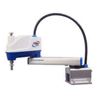
THL600
Toshiba THL600 Manuals
Manuals and User Guides for Toshiba THL600. We have
3
Toshiba THL600 manuals available for free PDF download: Instruction Manual
Toshiba THL600 Instruction Manual (280 pages)
Industrial Robot
Brand:
Toshiba
| Category:
Robotics
| Size: 10.36 MB
Table of Contents
Table of Contents
7
Maintenance
13
Maintenance Schedule
13
Items for Maintenance and Inspection
14
Inspection at Power off (at Non-Operation)
14
Inspection at Power on (at Operation)
15
Overhaul
15
Cautions on Maintenance and Inspection
16
Maintenance Tools
16
Clamping Hexagon Socket Head Cap Screws and Set Screws
17
Maintenance Contract and Repair
18
Maintenance Contract
18
Repair
18
Modification
19
Maintenance of the Main Robot (THL300, THL400)
20
Details of Inspection
20
Check of each Bolt (or Screw) for Clamping
20
Check of each Cable and Air Tube for Abrasion
22
Check of Cable Clamp Tightening
23
Check of each Axis for Operation
24
Layout of Robot Components and Drive Mechanism
25
Dismounting and Mounting each Cover
26
Arm 2 Cover
27
Base Covers
28
Replacing Motor
31
Type of Motor
31
Motor Locations
32
Dismounting Axis 1 Motor
33
Mounting Axis 1 Motor
34
Dismounting Axis 2 Motor
37
Mounting Axis 2 Motor
39
Dismounting Axis 3 Motor
42
Mounting Axis 3 Motor
43
Dismounting Axis 4 Motor
45
Mounting Axis 4 Motor
47
Adjusting and Replacing Timing Belt
48
Type of Timing Belt
48
Timing Belt Locations
49
Replacing Axis 3 Timing Belt
49
Replacing Axis 4 Timing Belt
53
Check Timing Belt Adjustment
58
Filling Grease to Ball Screw Spline Unit and Replacement
59
Type of Ball Screw Spline Unit
59
Ball Screw Spline Unit Location
60
Greasing Ball Screw Spline Unit and Applying Anticorrosive
60
Dismounting Ball Screw Spline Unit
64
Mounting Ball Screw Spline Unit
68
Reduction Gear Replacement
71
Type of Reduction Gear
71
Reduction Gear Locations
72
Dismounting Axis 1 Reduction Gear
72
Mounting Axis 1 Reduction Gear
74
Dismounting Axis 2 Reduction Gear
77
Mounting Axis 2 Reduction Gear
78
Replacing Axis 4 Reduction Gear
80
Maintenance of the Main Robot (THL500, THL600, THL700)
82
Details of Inspection
82
Check of each Bolt (or Screw) for Clamping
82
Check of each Cable and Air Tube for Abrasion
84
Check of Cable Clamp Tightening
85
Check of each Axis for Operation
86
Layout of Robot Components and Drive Mechanism
87
Dismounting and Mounting each Cover
88
Arm 2 Cover
89
Base Covers
89
Replacing Motor
92
Type of Motor
92
Motor Locations
93
Dismounting Axis 1 Motor
94
Mounting Axis 1 Motor
95
Dismounting Axis 2 Motor
98
Mounting Axis 2 Motor
99
Dismounting Axis 3 Motor
102
Mounting Axis 3 Motor
103
Dismounting Axis 4 Motor
105
3.4.10 Mounting Axis 4 Motor
106
Adjusting and Replacing Timing Belt
107
Type of Timing Belt
107
Timing Belt Locations
108
Replacing Axis 3 Timing Belt
108
Replacing Axis 4 Timing Belt
111
Check Timing Belt Adjustment
114
Filling Grease to Ball Screw Spline Unit and Replacement
115
Type of Ball Screw Spline Unit
115
Ball Screw Spline Unit Location
116
Greasing Ball Screw Spline Unit and Applying Anticorrosive
116
Dismounting Ball Screw Spline Unit
119
Mounting Ball Screw Spline Unit
122
Reduction Gear Replacement
126
Type of Reduction Gear
126
Reduction Gear Locations
127
Dismounting Axis 1 Reduction Gear
127
Mounting Axis 1 Reduction Gear
129
Dismounting Axis 2 Reduction Gear
133
Mounting Axis 2 Reduction Gear
134
Replacing Axis 4 Reduction Gear
136
Maintenance of the Main Robot (THL800, THL900, THL1000)
138
Details of Inspection
138
Check of each Bolt (or Screw) for Clamping
138
Check of each Cable and Air Tube for Abrasion
140
Check of Cable Clamp Tightening
141
Check of each Axis for Operation
142
Layout of Robot Components and Drive Mechanism
143
Dismounting and Mounting each Cover
144
Arm 2 Cover
145
Base Covers
146
Replacing Motor
147
Type of Motor
147
Motor Locations
148
Dismounting Axis 1 Motor
149
Mounting Axis 1 Motor
151
Dismounting Axis 2 Motor
154
Mounting Axis 2 Motor
156
Dismounting Axis 3 Motor
159
Mounting Axis 3 Motor
161
Dismounting Axis 4 Motor
162
4.4.10 Mounting Axis 4 Motor
163
Adjusting and Replacing Timing Belt
165
Type of Timing Belt
165
Timing Belt Locations
166
Replacing Axis 3 Timing Belt
166
Replacing Axis 4 Timing Belt
169
Check Timing Belt Adjustment
173
Filling Grease to Ball Screw Spline Unit and Replacement
174
Type of Ball Screw Spline Unit
174
Ball Screw Spline Unit Location
175
Greasing Ball Screw Spline Unit and Applying Anticorrosive
175
Dismounting Ball Screw Spline Unit
178
Mounting Ball Screw Spline Unit
182
Reduction Gear Replacement
186
Type of Reduction Gear
186
Reduction Gear Locations
187
Dismounting Axis 1 Reduction Gear
187
Mounting Axis 1 Reduction Gear
188
Dismounting Axis 2 Reduction Gear
191
Mounting Axis 2 Reduction Gear
192
Replacing Axis 4 Reduction Gear
194
Maintenance of Controller (TSL3000)
196
Cautions on Maintenance and Inspection
196
Layout of Controller Parts
197
Maintenance Procedures
198
Check of Controller Air Vent Holes
198
Check of Safety Devices for Function
199
Battery Replacement
201
Replacement of Switching Power Supply Unit
203
Replacement of Fuse (X8YX Printed Board)
207
Replacement of Output Ics (X8YX Printed Board)
209
Maintenance of Controller (TSL3000E)
212
Cautions on Maintenance and Inspection
212
Layout of Controller Parts
213
Maintenance Procedures
214
Check of Controller Air Vent Holes
214
Check of Safety Devices for Function
215
Battery Replacement
217
Replacement of Switching Power Supply Unit
219
Replacement of Fuse (X8YJ Printed Board)
225
Maintenance of Controller (TS3000, TS3000E)
227
Cautions on Maintenance and Inspection
227
Layout of Controller Parts
228
Maintenance Procedures
230
Check of Controller Air Vent Holes
230
Check of Safety Devices for Function
231
Battery Replacement
233
Replacement of Switching Power Supply Unit
236
Replacement of Fuse (X8GN, X8GI Printed Board)
240
Replacement of Output Ics (X8GN, X8GI Printed Board)
241
Robot Home Point and Position Detector Error
244
Setting Robot Home Point
244
Position Detector Error
244
Replacing Position Detector (or Encoder) Batteries
248
Battery Box Location
249
Replacing Batteries
249
Battery Error Code
251
About Home Position
253
Locations of Robot Home Point Match-Marks (THL300,THL400)
253
Locations of Robot Home Point Mach-Mark (THL500, THL600 and THL700)
254
Locations of Robot Home Point Mach-Mark (THL800, THL900 and THL1000)
254
Home Position of 3 Axis (THL300 and THL400)
255
Home Position of 3 Axis (THL500, THL600 and THL700)
255
Home Position of 3 Axis (THL800, THL900 and THL1000)
255
Encoder Status Display
256
1] Encoder Error Reset Operation
257
2] Restoring Home Position Data by Multi-Turn Data Clear
258
3] Restoring Home Position Data by ZEROP Function
259
4]Restoring Home Position Data by HOME Function
262
Outline of HOME Function
262
Setting HOME1 and HOME2
263
How to Restore Data by HOME1 or HOME2
264
How to Restore Data by HOME3 or HOME4
266
Change for Home Position Data Form
268
Affirmation
270
Backup of Data
270
Replacement Parts for Maintenance
271
Cautions for Maintenance Replacement Parts
271
List of Replacement Parts - Main Robot (THL300, THL400)
272
List of Replacement Parts - Main Robot (THL500, THL600, THL700)
273
List of Replacement Parts - Main Robot (THL800, THL900, THL1000)
274
List of Replacement Parts - Controller (THL300,THL400/TSL3000)
275
List of Replacement Parts - Controller (THL500~THL1000/TSL3000)
276
List of Replacement Parts - Controller (THL300, THL400/TSL3000E)
277
List of Replacement Parts - Controller (THL500 to THL1000/TSL3000E)
278
List of Replacement Parts - Controller (THL300, THL400/TS3000, TS3000E)
279
List of Replacement Parts - Controller (THL500~THL1000/TS3000, TS3000E)
280
Advertisement
Toshiba THL600 Instruction Manual (255 pages)
Industrial Robot
Brand:
Toshiba
| Category:
Robotics
| Size: 10.24 MB
Table of Contents
Table of Contents
7
Specifications (THL300 and THL400)
12
Correspondence between the Robots and the Robot Controllers
12
Robot Configuration Diagram (TSL3000)
12
Robot Configuration Diagram (TSL3000E)
13
Robot Configuration Diagram (TS3000 and TS3000E)
14
Name of each Part
15
External Dimensions
16
Specifications Table
18
Specifications (THL500, THL600 and THL700)
20
Correspondence between Robot and Controller, and Equipment Configuration Diagram
20
Name of each Parts
20
External Dimensions
22
Specifications Table
25
Specifications (THL800, THL900 and THL1000)
27
Correspondence between Robot and Controller, and Equipment Configuration Diagram
27
Name of each Parts
27
External Dimensions
29
Specifications Table
32
Transportation (THL300 and THL400)
34
Unpacking (TSL3000)
34
Unpacking (TSL3000E)
36
Unpacking (TS3000 and TS3000E)
38
Transportation
40
Mass and Dimensions
40
Transporting the Robot
41
Transporting the Controller
42
Storage
43
Storage Precautions for the Robot
43
Storage Precautions for the Controller
43
Transportation (THL500, THL600 and THL700)
44
Unpacking (TSL3000)
44
Unpacking (TSL3000E)
46
Unpacking (TS3000 and TS3000E)
48
Transportation
49
Mass and Dimensions
49
Transporting the Robot
51
Transporting the Controller
53
Storage
54
Storage Precautions for the Robot
54
Storage Precautions for the Controller
54
Transportation (THL800, THL900 and THL1000)
55
Unpacking (TSL3000)
55
Unpacking (TSL3000E)
55
Unpacking (TS3000 and TS3000E)
58
Transportation
60
Mass and Dimensions
60
Transporting the Robot
62
Transporting the Controller
64
Storage
65
Storage Precautions for the Robot
65
Storage Precautions for the Controller
65
Robot Installation (THL300 and THL400)
66
Installation Environment
66
Installation
67
External Dimensions and Working Envelope
67
Changing the Operation Ranges of Axes 1 and 2
70
Changing the Operating Ranges of Axes 1 and 2
71
Changing the Operating Range of Axis 3
72
Changing Software Limits
78
Coordinate System
79
Installing the Robot
80
Precautions for Handling the Teach Pendant
81
Safety Measures
82
Robot Installation (THL500, THL600 and THL700)
83
Installation Environment
83
Installation
83
External Dimensions and Working Envelope
83
Changing the Operating Ranges of Axes 1 and 2
87
Changing the Operating Range of Axis 3
89
Changing Software Limits
95
Coordinate System
96
Installing the Robot
97
Precautions for Handling the Teach Pendant
98
Safety Measures
98
Robot Installation (THL800, THL900 and THL1000)
99
Installation Environment
99
Installation
99
External Dimensions and Working Envelope
99
Changing the Operating Range of Axis 3
105
Changing Software Limits
111
Coordinate System
112
Installing the Robot
113
Precautions for Handling the Teach Pendant
114
Safety Measures
114
Installing the Controller (TSL3000)
115
External Dimensions
115
Precautions for Direct Installation
116
Rack Mounting Dimensions
117
Precautions for Assembling the Control Panel
118
Installing the Controller (TSL3000E)
121
External Dimensions
121
Precautions for Direct Installation
122
Rack Mounting Dimensions
123
Precautions for Rack Mounting
124
Installing the Controller (TS3000 and TS3000E)
126
External Dimensions
126
Precautions for Direct Installation
127
Rack Mounting Dimensions
128
Precautions for Rack Mounting
128
System Connections (TSL3000)
132
Cable Wiring
132
Connector Arrangement on the Controller
132
Connecting the Power Cable "ACIN" ( of Fig. 13.1) (Plug Connector Attached)
133
Connecting the Motor Cable "ROBOT" ( of Fig. 13.1) (THL300 to THL1000)
134
Connecting the Encoder Cable "ROBOT" ( of Fig. 13.1)
135
Connecting the Robot Control Signal Cable "ROBOT" ( of Fig. 13.1)
135
Connecting the Brake Signal Cable "ROBOT" ( of Fig. 13.1)
135
Connecting the External Input/Output Power Cable "GNDP24V" ( of Fig. 13.1)
136
Connecting and Disconnecting Cables
137
Examples of Connector Terminal Arrangement (Controller Side)
139
Controller Connector Signals
141
Connector Signal Connection Diagrams
141
Jumpers for Safety Related Signals
141
System Connections (TSL3000E)
143
Cable Wiring
143
Connector Arrangement on the Controller
143
Connecting the Power Cable
144
Connecting the Motor Cable/Encorder Cable
145
Connecting the Brake Signal Cable and the Robot Control Signal Cable
146
Connecting the External Input/Output Power Cable
146
Connecting and Disconnecting Cables
147
Examples of Connector Terminal Arrangement (for the TSL3000E)
150
Controller Connector Signals
153
Connector Signal Connection Diagrams
153
Jumpers for Safety Related Signals
153
System Connections (TS3000 and TS3000E)
155
Cable Wiring
155
Connector Arrangement on the Controller
155
Connecting the Power Cable "ACIN" ( of Fig. 15.1) (Plug Connector Attached)
156
Connecting the Motor Cable "MOTOR" ( of Fig. 15.1) (THL300 to THL1000)
157
Connecting the Encoder Cable "ENC" ( of Fig. 15.1)
158
Connecting the Robot Control Signal Cable "HAND" ( of Fig. 15.1)
158
Connecting the Brake Signal Cable "BRK" ( of Fig. 15.1)
159
Connecting the External Input/Output Power Cable "EMS" ( of Fig. 15.1)
159
Connecting and Disconnecting Cables
160
Examples of Connector Terminal Arrangement (Controller Side)
162
Controller Connector Signals
165
Connector Signal Connection Diagrams
165
Jumpers for Safety Related Signals
165
Separating Control Panel from Controller
167
Removing Control Panel
167
Cable between Controller and Control Panel (Option)
167
Control Panel Mounting Dimensions
168
Mounting Dummy Panel on Controller (Option)
169
Dimensions When Separating Control Panel
170
Tool Interface (THL300 and THL400)
171
Mounting Tool
171
Tool Air Piping
172
Permissible Load Conditions and Program Setting
173
Permissible Load Conditions
173
Load Conditions and Program Setting
174
Setting Maximum Speed and Robot Acceleration/Deceleration for Load Conditions
178
Tool Interface (THL500, THL600 and THL700)
184
Mounting Tool
184
Tool Air Piping
185
Permissible Load Conditions and Program Setting
186
Permissible Load Conditions
186
Load Conditions and Program Setting
187
Setting Maximum Speed and Robot Acceleration/Deceleration for Load Conditions
187
Tool Interface (THL800, THL900 and THL1000)
197
Mounting Tool
197
Tool Air Piping
198
Permissible Load Conditions and Program Setting
199
Permissible Load Conditions
199
Load Conditions and Program Setting
200
Setting Maximum Speed and Robot Acceleration/Deceleration for Load Conditions
200
Tool Interface (TSL3000)
210
Tool Wiring
210
Tool Signals (Controller Side)
221
Tool Interface (TSL3000E)
225
Tool Wiring
225
Tool Signals (Controller Side)
236
Tool Interface (TS3000 and TS3000E)
240
Tool Wiring
240
Tool Signals (Controller Side)
252
Toshiba THL600 Instruction Manual (29 pages)
Industrial Robot, Robot Controller
Brand:
Toshiba
| Category:
Robotics
| Size: 0.86 MB
Advertisement
Advertisement
Related Products
Toshiba THL Series
Toshiba THL300
Toshiba THL400
Toshiba THL500
Toshiba THL700
Toshiba THL800
Toshiba THL900
Toshiba THL1000
Toshiba TH450A-T
Toshiba TH1200A
Toshiba Categories
Laptop
Air Conditioner
TV
LCD TV
All in One Printer
More Toshiba Manuals
Login
Sign In
OR
Sign in with Facebook
Sign in with Google
Upload manual
Upload from disk
Upload from URL