Sign In
Upload
Manuals
Brands
Asus Manuals
Server
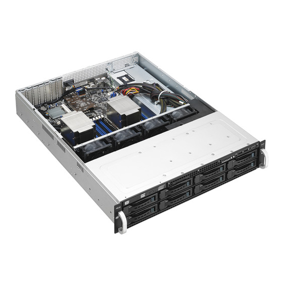
RS520-E8-RS8 V2
Asus RS520-E8-RS8 V2 Manuals
Manuals and User Guides for Asus RS520-E8-RS8 V2. We have
1
Asus RS520-E8-RS8 V2 manual available for free PDF download: User Manual
Asus RS520-E8-RS8 V2 User Manual (206 pages)
Brand:
Asus
| Category:
Network server
| Size: 10.74 MB
Table of Contents
Table of Contents
3
Notices
7
Reach
7
Safety Information
8
Australia Statement Notice
9
About this Guide
10
Chapter 1: Product Introduction
13
System Package Contents
14
Serial Number Label
15
System Specifications
16
Front Panel Features
18
Rear Panel Features
19
Internal Features
21
LED Information
23
Front Panel Leds
23
LAN (RJ-45) Leds
24
HDD Status LED
24
Chapter 2: Hardware Information
25
Chassis Cover
26
Central Processing Unit (CPU)
27
Installing the CPU
27
System Memory
33
Overview
33
Memory Configurations
33
Installing a DIMM
35
Removing a DIMM
35
Hard Disk Drives
36
Installing a 3.5-Inch HDD
36
Installing a 2.5-Inch SSD (RS520-E8-RS12-EV2 Only)
37
Expansion Slot
39
Installing an Expansion Card to the PCI-E Slot
39
Installing an ASUS PIKE II Card (RS520-E8-RS8 Only)
41
Installing an M.2 Expansion Card
45
Installing a Mezzanine Card
46
Configuring an Expansion Card
48
Cable Connections
49
Backplane Cabling
50
Removable/Optional Components
52
System Fans
52
Redundant Power Supply Module
55
Chapter 3: Installation Options
57
Tool-Less Friction Rail Kit
58
Chapter 4: Motherboard Information
61
Motherboard Layout
62
Jumpers
64
Clear RTC RAM (3-Pin CLRTC1)
64
VGA Controller Setting (3-Pin VGA_SW1)
65
LAN Controller Setting (3-Pin LAN_SW1, LAN_SW2)
65
ME Firmware Force Recovery Setting (3-Pin ME_RCVR1)
66
DDR4 Thermal Event Setting (3-Pin DIMMTRIP1)
66
Internal Connectors Page
68
Serial ATA 6.0 / 3.0 Gbps Connector (7-Pin SATA6 [Light Blue])
68
Power Supply Smbus Connector (5-Pin PSUSMB1)
68
USB 2.0 Connector (10-1 Pin USB56; USB7)
69
USB 3.0 Connector (20-1 Pin USB3_34)
69
CPU, Front, and Rear Fan Connectors
70
Frnt_Fan5, Rear_Fan1, Rear_Fan2)
70
LAN Activity LED Connector (5-1 Pin LAN34_LED1)
70
Serial Port Connector (10-1 Pin COM1)
71
Trusted Platform Module Connector (20-1 Pin TPM1)
71
ATX Power Connectors (24-Pin EATXPWR1, 8-Pin EATX12V1, 8-Pin EATX12V2)
72
System Panel Connector (20-1 Pin PANEL1)
73
Auxiliary Panel Connector (20-2 Pin AUX_PANEL1)
74
VGA Connector (10-1 Pin VGA_HDR1)
75
Hard Disk Activity LED Connector (4-Pin HDLED1)
75
Chassis Intrusion (2-Pin INTRUSION1)
76
ISATA & ISSATA Connectors (ISATA; ISSATA)
76
NGFF) Connector (NGFF1)
77
Mezzanine PCI Card Connector (MEZZ1)
77
Internal Connectors
68
Onboard Leds
78
Onboard Leds Page
78
Standby Power LED (SBPWR1)
78
Baseboard Management Controller LED (BMCLED1)
78
CPU Warning LED (ERRCPU1, ERRCPU2)
79
Location LED (LOCLED1)
79
Memory Error LED
80
Catt Led (Catterr_Led1)
80
Message LED (MESLED1)
81
OCPLAN Activity LED Connector (4-Pin OCP_LED1)
81
Chapter 5: BIOS Setup
83
Managing and Updating Your BIOS
84
ASUS Crashfree BIOS 3 Utility
84
ASUS EZ Flash 2 Utility
85
BUPDATER Utility
86
BIOS Setup Program
88
BIOS Menu Screen
89
Menu Bar
89
Menu Items
90
Submenu Items
90
Navigation Keys
90
General Help
90
Configuration Fields
90
Pop-Up Window
90
Scroll Bar
90
Main Menu
91
System Date [Day XX/XX/XXXX]
91
System Time [XX:XX:XX]
91
Advanced Menu
92
ACPI Settings
93
Smart Settings
93
NCT6779D Super IO Configuration
94
Intel LAN I210 Configuration
95
Serial Port Console Redirection
96
Apm
99
PCI Subsystem Settings
100
Network Stack Configuration
101
CSM Configuration
102
Trusted Computing
103
USB Configuration
104
Iscsi Configuration
105
Intelrcsetup Menu
106
Processor Configuration
107
Advanced Power Management Configuration
109
Common Refcode Configuration
110
QPI Configuration
111
Memory Configuration
112
IIO Configuration
115
PCH Configuration
116
Miscellaneous Configuration
120
Server ME Configuration
120
Runtime Error Logging Support
121
Server Mgmt Menu
121
Event Logs Menu
126
Change Smbios Event Log Settings
126
View Smbios Event Log
127
Monitor Menu
128
Security Menu
129
Boot Menu
132
Tool Menu
133
Exit Menu
134
Chapter 6: RAID Configuration
137
Setting up RAID
138
RAID Definitions
138
Installing Hard Disk Drives
139
Setting the RAID Item in BIOS
139
RAID Configuration Utilities
139
LSI Software RAID Configuration Utility
140
Creating a RAID Set
141
Adding or Viewing a RAID Configuration
147
Initializing the Virtual Drives
148
Rebuilding Failed Drives
152
Checking the Drives for Data Consistency
154
Deleting a RAID Configuration
157
Selecting the Boot Drive from a RAID Set
158
Enabling Writecache
159
Intel
160
ROM Utility
160
Creating a RAID Set
161
Deleting a RAID Set
163
Resetting Disks to Non-RAID
164
Exiting the Intel Rapid Storage Technology Enterprise SATA Option ROM Utility
165
Rebuilding the RAID
165
Setting the Boot Array in the BIOS Setup Utility
167
Intel ® Rapid Storage Technology Enterprise (Windows)
168
Creating a RAID Set
169
Changing a Volume Type
171
Deleting a Volume
172
Preferences
173
Chapter 7: Driver Installation
175
RAID Driver Installation
176
Creating a RAID Driver Disk
176
Installing the RAID Controller Driver
178
Management Applications and Utilities Installation
188
Running the Support DVD
188
Intel ® Chipset Device Software Installation
192
Adapters Driver
194
VGA Driver Installation
197
Intel ® Rapid Storage Technology Enterprise 4.0 Installation
199
Appendices
203
ASUS Contact Information
204
Advertisement
Advertisement
Related Products
Asus RS520-E6 - 0 MB RAM
Asus RS520-E6 RS8
Asus RS520-E8-RS12-E
Asus RS520-E8-RS8
Asus RS520-E6 ERS8
Asus RS520-E8-RS12-EV2
Asus RS520-E9-RS12-E
Asus RS520-E9-RS8
Asus RS520-X5 PS8
Asus RS500-E9-RS4
Asus Categories
Motherboard
Laptop
Desktop
Monitor
Network Router
More Asus Manuals
Login
Sign In
OR
Sign in with Facebook
Sign in with Google
Upload manual
Upload from disk
Upload from URL