Sign In
Upload
Manuals
Brands
Toshiba Manuals
Telephone System
Strara CTX Series
Toshiba Strara CTX Series Manuals
Manuals and User Guides for Toshiba Strara CTX Series. We have
1
Toshiba Strara CTX Series manual available for free PDF download: Installation And Maintenance Manual
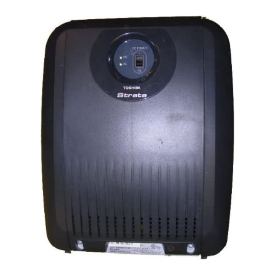
Toshiba Strara CTX Series Installation And Maintenance Manual (290 pages)
Digital Business Telephone Systems
Brand:
Toshiba
| Category:
Telephone System
| Size: 4.66 MB
Table of Contents
Table of Contents
3
Chapter 3 - Strata CTX670 Installation
11
Introduction
11
Organisation
11
Conventions
12
Related Documents/Media
13
General Description
13
Installation and Programming
13
User Guides
13
Quick Reference Guides
13
CD-Roms
13
Chapter 1 - Strata CTX Configuration
15
Strata CTX100 Overview
15
CTX100 Processor
16
Cpu/Memory
16
Large Scale Integrated (LSI) Circuits
16
Memory Protection Battery
16
Relay Control Interface
16
Music-On-Hold/Background Music Interface
16
Smartmedia Memory
17
CTX100 Processor Optional Subassemblies
17
CTX100 Cabinet Slots
17
Base Cabinet
17
Expansion Cabinets
17
CTX100 License Control
18
Licensed Software Options
18
Strata CTX670 Overview
19
CTX670 Processor Pcbs
19
Cpu/Memory
19
Large-Scale Integrated (LSI) Circuits
20
Memory Protection Battery
20
Music-On-Hold/Background Music Interface
20
Smartmedia Memory
20
Network Interface
20
Maintenance Modem
20
CTX670 Processor PCB Subassemblies
21
CTX670 License Control
21
Licensed Software Options
22
CTX670 Cabinet Slots
22
Base Cabinet
22
Expansion Cabinets
23
CTX670 Remote Expansion Cabinet
23
System Capacities
24
Strata CTX100 Cabinet Slot Configuration Considerations
35
CTX100 Base Only: Digital Telephones and PRI Lines
36
CTX100 Base & Expansion: Digital Telephones and PRI Lines
36
Strata CTX670 Cabinet Slot Configuration
37
PCB Placement Guidelines
38
System Power Factor Check Considerations
41
Cabinet Power Factor Check
43
Ctx100
43
Ctx670
44
CTX Primary AC and Reserve Power Considerations
45
CTX100 AC Power Considerations
45
CTX670 AC Power Considerations
45
Reserve Power (CTX100 and CTX670)
46
Primary/Reserve Power Cabinet Hardware
47
Hardware Compatibility
49
Chapter 2 - Strata CTX100 Installation
53
Inspection
53
Packaging and Storage
53
Site Requirements
53
Input Power
53
Cabinet Size and Weight
54
Clearance and Location
54
Environmental Considerations
56
AC Power and Earthing Requirements
56
AC Power and "PROTECTIVE EARTH" Test
57
Installing the CTX100 Cabinet
57
Step 1: Remove Cabinet Covers
57
Step 2: Remove the Back Cover from the Cabinet(S)
57
Step 3: Check the Base/Expansion Power Supply Jumper Plug
58
Step 4: Mount the Base Cabinet
58
Step 5: Mount the Expansion Cabinet (if Required)
60
Step 6: Install Reserve Power
62
Step 7: Check Power Supply Circuit Breakers and Fuses
65
Step 8: Set Jumpers and Install Option Pcbs Onto the ACTU
69
Step 9: Install the Main Processor (ACTU) PCB
70
Step 10: Install Other Pcbs into the Cabinet(S)
71
Step 11: Attach and Route PCB Cables
73
Power Considerations
78
Reserve Power
78
EU Registration Information
79
Cabinet Installation Considerations
80
Recommended Installation Sequence
80
Step 1: Install Power Supply
80
Check the -24 Volt Circuit Breakers
81
Check the Power Factor Indicator and Reset Button
82
Power Supply (BPSU672) Removal
82
Power Supply Replacement
82
Step 2: Mount Cabinets
84
Wall Mounting the Base (Top) Cabinet
84
Wall Mounting Expansion Cabinets
85
Step 3: Install Data Cables
90
Step 4: Ground the System
92
Step 5: Install AC Power Components
94
AC Power Requirements
94
Step 6: Install Reserve Power
97
Reserve Battery Cabinet Components/Cables
98
Reserve Power for One or Two Cabinets (Wall Mount)
98
Reserve Power for Three or more Cabinets (Wall Mount)
99
Cabinet Floor Mounting
101
Reserve Power/Ac Wiring for Three or more Cabinets (Floor Mount)
109
Step 7: Install Processor and Universal Pcbs
109
PCB Installation Considerations
110
PCB Option Considerations
110
BECU/BBCU Installation
110
Remote Expansion Cabinet Unit
116
Remote Cabinet Installation Instructions
117
Status Indicators
121
Monitor Port Communication Parameters
122
Monitor Port Pin Assignments
122
Chapter 4 - PCB Installation
123
PCB Chapter Layout
123
PCB Hardware/Software Options
124
PCB Hardware Options
124
PCB Software Options
124
CTX100 ACTU Processor Pcbs
124
CTX670 BECU/BBCU Processor Pcbs
124
PCB Installation Power Supply Considerations
124
ADKU Hardware Options
125
ADKU Installation
125
ASTU Installation
125
BDKU Hardware Options
127
Bdks
127
BDKU Installation
127
BIOU Installation
129
BVPU Configuration
131
BVPU Installation
131
PDKU2 Hardware Options
133
PDKU2 Installation
133
R48S -48 Volt Supply Installation (Internal Option)
134
External Options
135
RSTU Installation
135
RCOS Installation (Internal Option)
137
RCOU Installation
139
REMU2A - Tie Line Unit
143
REMU2A Installation
143
PEMU Installation
143
PACU - AC15 Tie Line Unit
147
PACU Installation
147
Chapter 5 - ISDN Interfaces
149
PRI Overview
149
BRI S/T Overview
149
Strata CTX ISDN Reference Model
150
RPTU Interface Unit
151
RPTU Overview
151
Slot Assignments
151
RPTU Installation
151
Cabling
154
RBSU/RBSS Interface Units
157
Overview
157
Capacity and Cabinet Slot Information
158
PS-1 Backup Power Option
158
RBSU/RBSS Installation
159
Modular Jack Pin Configurations
162
RBSU/RBSS Premise Wiring Guidelines
163
Connecting RBSU to Network Side (TE-Mode)
165
Connecting RBSU/RBSS Station Devices (NT-Mode)
166
RBSU/RBSS Passive Bus Configurations
168
Timing and Synchronisation
169
PRI/BRI Call Monitoring
170
Call Monitor Output for ISDN
171
BRI Call Monitor
174
Chapter 6 - MDF PCB Wiring
177
Station Loop Lengths
178
Station Wiring Diagrams
180
ADKU and BDKU/BDKS Digital Station Wiring
181
PDKU Digital Station Wiring
182
Digital Telephone DSS and DDCB External Power Connection
185
RSTU or PSTU Analogue Devices Wiring
187
Power Failure Cut through (DPFT) Wiring Pin-Outs
189
Exchange Line Wiring Diagrams
191
RCOU/RCOS Wiring
192
PEMU Wiring
195
Option Interface PCB Wiring Diagram
198
Chapter 7 - Station Apparatus
199
3000/3500-Series Digital Telephones
200
Telephone Installation
201
Digital Telephone System Connection
201
3000/3500-Series Telephone Option Pcbs
202
Telephone Speaker Off-Hook Call Announce Upgrade (BVSU)
204
Telephone Headset (BHEU) Upgrade
206
Telephone Option Straps
207
TAPI and Simultaneous Voice and Data Upgrades for 3000/3500-Series Telephones (BPCI)
209
3000/3500-Series Telephone Settings
210
Telephone Programming Mode a
214
Telephone Program Option Reset
214
Dial Pad and Button Beeps
214
Speakerphone/Microphone Sensitivity Adjustment
215
Call Waiting and Camp-On Ring Tone over Handset/Headset Option
215
DKT2000/2500 Mode On/Off
215
Redial/Feature Button Activation/Deactivation (DKT3001 Only)
216
Msg/Feature Button Activation/Deactivation (DKT3001 Only)
216
Test the Display on Large LCD Telephones (DKT3014-SDL Only)
217
Reset and Adjust the LCD Contrast
217
Country Settings On/Off
217
Digital Add-On Module Installation
218
Tilt Stands and Wall Mounting
220
Tilt Stand Installation with Add-On Modules
221
Tilt Stand for DKT + 2 Adms
223
Telephone Wall Mounting
224
Direct Station Selection (DSS) Console/System Connection
226
DSS Console Connections
226
Standard Telephones
227
Cordless Digital Telephones
227
Dkt2004-Ct
227
Precautions
228
Dkt2104-Ct
229
Cordless Telephone Installation (DKT2004-CT and DKT2104-CT)
229
Telephone Cord Connection
230
Connect and Apply Power to Base Unit
230
Cordless Telephone Connectors
231
Handset Battery Pack Installation
232
Removing and Charging Your Battery Pack
232
Tips on Extending Battery Pack Life
233
2000/2500-Series Telephones
234
2000/2500-Series Telephone Option Pcbs
234
Telephone Speaker Off-Hook Call Announce Upgrade (DVSU)
235
HHEU Installation
236
Carbon Headset/Handset Straps
239
Beep Strap
239
Microphone/Speaker Sensitivity Adjustment (Speakerphones Only)
239
Busy Override and Camp-On Ring Tone over Handset/Headset Option
240
External Power Straps
240
DIP Switches
241
DKT2020-FDSP Full-Duplex Speakerphone with External Microphone
242
Digital Single Line Telephone (DKT2001 Only)
246
Chapter 8 - Peripheral Installation
247
Application PC and Server Interfaces
247
Network Interface Connections
248
Music-On-Hold/Background Music Interfaces
254
External Page with BIOU Interface
256
Control Relays with BIOU Interface
259
Door Phone/Door Lock with DDCB Interface
260
DDCB and MDFB Cabling
260
DDCB Wall Mounting
260
Door Phone Wire Connections
260
Calling from a Door Phone
261
Calling a Door Phone
261
Door Lock Control
261
Door Phone/Lock Programming
261
MDFB Wall Mounting
261
External Speaker Unit (HESB) Options
263
Telephone External Ringer
263
Telephone (BHEU) to External Speaker (HESB) Cable Connection
264
Amplified Page Speaker Option
267
Talkback Amplified Page Speaker with Talkback Option
269
HESB Wall Mounting
271
T001B Relay Unit Options
271
System Hardware Requirements
271
T001B Installation
272
T001B Relay Unit Test
272
Power Failure Transfer Unit
273
Power Failure Emergency Transfer (DPFT) Installation
274
Station Message Detail Recording (SMDR)
275
SMDR Record Types
275
Advertisement
Advertisement
Related Products
Toshiba Strara CTX100
Toshiba Strara CTX670
Toshiba Strata AirLink
Toshiba Strata CT Digital Business Telephone Solutions
Toshiba StrataDK280
Toshiba Strata CTX ACD System
Toshiba Strata CIX LUCA
Toshiba Strata S
Toshiba Strata CIX LVMU
Toshiba Strata VI Series
Toshiba Categories
Laptop
Air Conditioner
TV
LCD TV
All in One Printer
More Toshiba Manuals
Login
Sign In
OR
Sign in with Facebook
Sign in with Google
Upload manual
Upload from disk
Upload from URL